
Putting it all together
If you want to jump in and start building the NaV-1 Synthesizer, this is the place to start! If you would like to see the design process from the beginning go HERE.
If you have been following the NaV-1 project over the last several months, you have seen the design slowly come together and hopefully gained some insight into the design process. There have been changes and re-designs along the way. Now the hardware part of our project is complete and set in stone. So lets build a final version.
Buying the Soundgin / Babblebot chip
This is the only relatively hard to get component on this project. Therefore it should be the first thing you acquire. If you can't get your hands on one of these, this project is going nowhere fast. Please read this article about buying the chip. I have had great luck ordering through speechchips.com.
Stripboard Construction
I wanted this project to be build-able by anyone with a soldering iron and some motivation. So with that in mind, I decided not to use a custom printed circuit board (PCB) and go with an off the shelf solution.
Stripboards (or Veroboards) are a great way to build up permanent versions of your electronic designs. If you've never used one, the video below is a great primer.
The Video
Instead of writing a small novel on all the details of constructing this project, I thought it would be better to show you. The following video will show you in great detail the techniques required to build this project. It is also a good primer on Stripboard construction and electronics assembly in general.
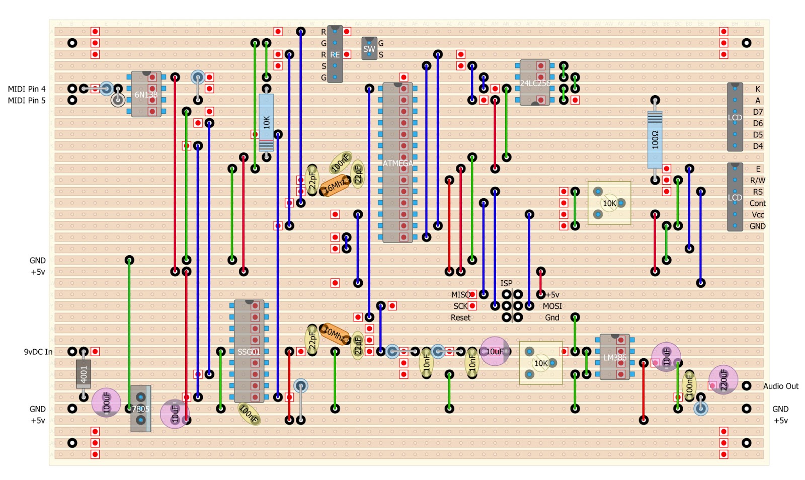
Schematic and Stripboard Diagram

The Code
Download the software for the NaV-1 HERE
Operation
After you have completed the project build, this video will show you how to put the NaV-1 to use.
Parts List
Integrated Circuits
1 - SSG01 Soundgin (or Babblebot) - Sound Processor Chip
1 - ATMEGA328P - Microcontroller
1 - 6N138 - Optocoupler
1 - 24LC256 - EEPROM
1 - LM386 - Audio Power Amplifier
1 - LM7805 - Voltage Regulator
1 - LCD Display 20x4 w/Backlight (HD44780 Compatible)
Semiconductors
1 - 1N4001 - Rectifier Diode
1 - 1N914 - Diode
1 - 16Mhz - Crystal
1 - 10Mhz - Crystal
Electrolytic Capacitors
1 - 220uF
1 - 100uF
3 - 10uF
Capacitors - Ceramic
3 - 100nF
2 - 10nF
4 - 22pF
Resistors - 1/4 Watt
2 - 27K Ohm
1 - 270 Ohm
1 - 220 Ohm
1 - 10K Ohm
1 - 1K Ohm
1 - 100 Ohm
1 - 10 Ohm
2 - 10K Ohm Trim Potentiometer
Hardware
1 - Rotary Encoder w/ Push Button - Panel Mount
1 - Push Button - Momentary, Normally Open - Panel Mount
1 - 5 Pin Din Socket (MIDI)
1 - 2.1mm Power Jack
1 - 1/4" Phone Jack (Mono)
2 - Header - 6 Position - .100" Straight (Mode Electronics #37-6206-3)
1 - Header - 5 Position - .100" Straight
1 - Header - 2 Position - .100" Straight
1 - Header - 2x6 Straight
2 - Connector - 6 Position w/Crimp Pins (Mode Electronics #37-606-3)
1 - Connector - 5 Position w/Crimp Pins
1 - Connector - 2 Position w/Crimp Pins
2 - DIP IC Socket - 8 Pin
1 - DIP IC Socket - 18 Pin
1 - DIP IC Socket - 28 Pin
1 - Stripboard - 38 x 62 Holes - 0.1"(2.54mm) Centers
1 - Ribbon Cable - (6 wires or more)
1 - Roll - AWG 22 Stranded Wire
3 - Roll - AWG 22 Solid Wire (Red, Green, Blue)
1 - 9v DC Power Adapter (500mA or Greater)
You did a great job,specialy the stripboard layout.what software did you use to make it
ReplyDeleteThanks Roy! I created the stripboard with a free program called diy-layout-creator (diylc).
DeleteI have gone through your website. I saw affiliate ads, rather than becoming an affiliate i suggest you to introduce contextual ads in your web.
ReplyDeletehttp://www.allevaconstruction.com/
More specs on the Capacitors please! They are hard to buy.
ReplyDeleteWhich caps are you having trouble finding?
DeleteWoW! Dave! You've gone to all the hassle of building the module that I would have inadvertently built myself, in my effort to get some valuable usage from my recently acquired SoundGin! I Love this inclusion of your RAW Edit mode, an though I haven't gone to the data sheet to compare the chip's abilities with your well-planned parameters, it seems you're module grants access to all 100% of itself? I saw that this chip has a 'speech' or 'voice' mode, who's functions are geared more towards the language and speech side of things, and it's 'synth' mode really seemed to grant more flexibility in usage still. Is there any added benefit you could think of to add a switch between these two modes?
ReplyDeleteOnce more, AWESOME JOB! Keep up your delightful projects, it's keeping DIY alive!!
James
Hello! Great project!
ReplyDeleteCan you please share the schematics as a Fritzing or Sprint Lay6 format?
Or Eagle? :)
ReplyDeleteThe software cant be found and the sound chip is also missing!!
ReplyDeleteIs there a replacement for "- SSG01 Soundgin (or Babblebot) - Sound Processor Chipc"? Can't find any on the net, beside data sheeds.
ReplyDeleteHello! I realy excited by your project, but I can't find code on github by the link... Where can I find actual link to code...&
ReplyDeleteI’d have to check with you here. Which is not something I usually do! I enjoy reading a post that will make people think. Also, thanks for allowing me to comment!
ReplyDeleteClick Here
Visit Web
Chillispot.org
Information
I really found this to much informatics. It is what i was searching for. แทงบอลออนไลน์
ReplyDelete